Hikvision
Adgangskontrolsystem
DS-K3B801BX-L
Hikvision DS-K3B801BX-L Brugsanvisning
Her er Hikvision DS-K3B801BX-L (Adgangskontrolsystem) brugervejledning. 2 sider på sprog Engelsk med en vægt på 1,463,020.0 Mb. Hvis du ikke kan finde svar på dit problem Spørg vores community.
Side 1/2
DS-K3B801BX Series
Swing Barrier
Quick Start Guide
UD31569B
©2022 Hangzhou Hikvision Digital Technology Co., Ltd. All rights reserved.
About this Manual
The Manual includes instructions for using and managing the Product. Pictures, charts,
images and all other information hereinafter are for description and explanation only.
The information contained in the Manual is subject to change, without notice, due to
firmware updates or other reasons. Please find the latest version of this Manual at the
Hikvision website (https://www.hikvision.com/).
Please use this Manual with the guidance and assistance of professionals trained in
supporting the Product.
Trademarks
and other Hikvision’s trademarks and logos are the properties of Hikvision in
various jurisdictions.
Other trademarks and logos mentioned are the properties of their respective owners.
Disclaimer
TO THE MAXIMUM EXTENT PERMITTED BY APPLICABLE LAW, THIS MANUAL AND THE
PRODUCT DESCRIBED, WITH ITS HARDWARE, SOFTWARE AND FIRMWARE, ARE PROVIDED
“AS IS” AND “WITH ALL FAULTS AND ERRORS”. HIKVISION MAKES NO WARRANTIES,
EXPRESS OR IMPLIED, INCLUDING WITHOUT LIMITATION, MERCHANTABILITY,
SATISFACTORY QUALITY, OR FITNESS FOR A PARTICULAR PURPOSE. THE USE OF THE
PRODUCT BY YOU IS AT YOUR OWN RISK. IN NO EVENT WILL HIKVISION BE LIABLE TO YOU
FOR ANY SPECIAL, CONSEQUENTIAL, INCIDENTAL, OR INDIRECT DAMAGES, INCLUDING,
AMONG OTHERS, DAMAGES FOR LOSS OF BUSINESS PROFITS, BUSINESS INTERRUPTION,
OR LOSS OF DATA, CORRUPTION OF SYSTEMS, OR LOSS OF DOCUMENTATION, WHETHER
BASED ON BREACH OF CONTRACT, TORT (INCLUDING NEGLIGENCE), PRODUCT LIABILITY,
OR OTHERWISE, IN CONNECTION WITH THE USE OF THE PRODUCT, EVEN IF HIKVISION
HAS BEEN ADVISED OF THE POSSIBILITY OF SUCH DAMAGES OR LOSS.
YOU ACKNOWLEDGE THAT THE NATURE OF THE INTERNET PROVIDES FOR INHERENT
SECURITY RISKS, AND HIKVISION SHALL NOT TAKE ANY RESPONSIBILITIES FOR ABNORMAL
OPERATION, PRIVACY LEAKAGE OR OTHER DAMAGES RESULTING FROM CYBER-ATTACK,
HACKER ATTACK, VIRUS INFECTION, OR OTHER INTERNET SECURITY RISKS; HOWEVER,
HIKVISION WILL PROVIDE TIMELY TECHNICAL SUPPORT IF REQUIRED.
YOU AGREE TO USE THIS PRODUCT IN COMPLIANCE WITH ALL APPLICABLE LAWS, AND
YOU ARE SOLELY RESPONSIBLE FOR ENSURING THAT YOUR USE CONFORMS TO THE
APPLICABLE LAW. ESPECIALLY, YOU ARE RESPONSIBLE, FOR USING THIS PRODUCT IN A
MANNER THAT DOES NOT INFRINGE ON THE RIGHTS OF THIRD PARTIES, INCLUDING
WITHOUT LIMITATION, RIGHTS OF PUBLICITY, INTELLECTUAL PROPERTY RIGHTS, OR DATA
PROTECTION AND OTHER PRIVACY RIGHTS. YOU SHALL NOT USE THIS PRODUCT FOR ANY
PROHIBITED END-USES, INCLUDING THE DEVELOPMENT OR PRODUCTION OF WEAPONS
OF MASS DESTRUCTION, THE DEVELOPMENT OR PRODUCTION OF CHEMICAL OR
BIOLOGICAL WEAPONS, ANY ACTIVITIES IN THE CONTEXT RELATED TO ANY NUCLEAR
EXPLOSIVE OR UNSAFE NUCLEAR FUEL-CYCLE, OR IN SUPPORT OF HUMAN RIGHTS
ABUSES.
IN THE EVENT OF ANY CONFLICTS BETWEEN THIS MANUAL AND THE APPLICABLE LAW,
THE LATTER PREVAILS.
Data Protection
During the use of device, personal data will be collected, stored and processed. To
protect data, the development of Hikvision devices incorporates privacy by design
principles. For example, for device with facial recognition features, biometrics data is
stored in your device with encryption method; for fingerprint device, only fingerprint
template will be saved, which is impossible to reconstruct a fingerprint image.
As data controller, you are advised to collect, store, process and transfer data in
accordance with the applicable data protection laws and regulations, including without
limitation, conducting security controls to safeguard personal data, such as,
implementing reasonable administrative and physical security controls, conduct periodic
reviews and assessments of the effectiveness of your security controls.
1System Wiring
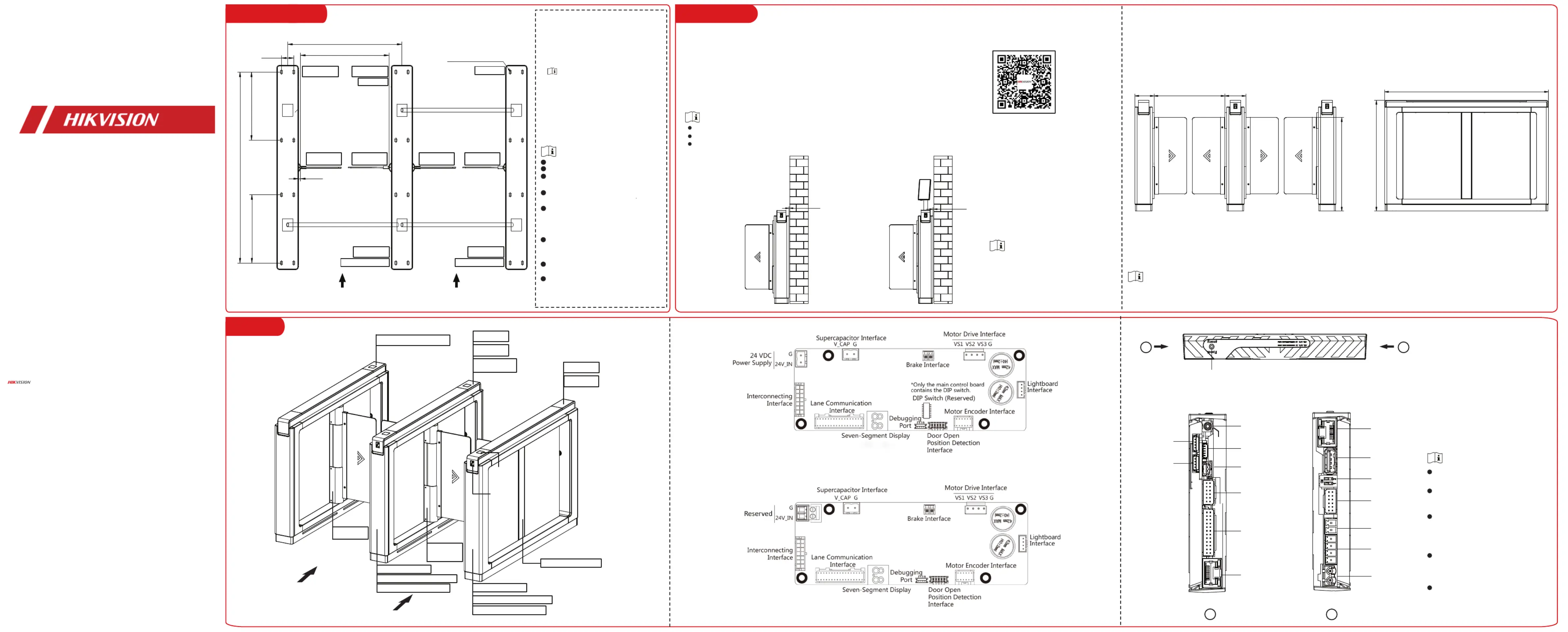
2Installation
3
Wiring
1. Draw a central line on the installation
surface of the left or right pedestal.
2. Draw other parallel lines for installing
the other pedestals.
The distance between the nearest
two lines is L + 190 mm. L represents
the lane width.
3. Slot on the installation surface and dig
installation holes according to the hole
position. Put 8 expansion bolts of
M12*120 for each pedestal.
4. Bury cables. Each lane buries 1 high
voltage cable and 1 low voltage cable. For
details, see the system wiring diagram.
High voltage: AC power input
Low voltage: interconnecting cables
The supplied interconnecting cables is 5.5 m
in length.
The suggested inner diameter of the low
voltage conduit is larger than 30 mm.
If you want to bury both of the AC power cord
and the low voltage cable, the two cables
should be in separated conduits to avoid
interference.
If more peripherals are required to connect,
you should increase the conduit diameter or
bury another conduit for the external cables.
The external AC power cord should be
double-insulated.
The network cable must be CAT5e or the
network cable has better performance.
Steps:
Steps:
1. Prepare installation tools and clean the installation base.
2. Disassemble the pedestal and keep the disassembled components and screws.
3. Drill holes on the ground according to the installation holes on the pedestals and
insert the expansion sleeves.
4. According to the entrance and exit marks on the pedestals, move the pedestals to
the corresponded positions.
5. Secure each pedestal with 8 nuts.
6. After installation, assemble the components and screws back to the pedestal.
Make sure the device is installed on flat surface.
Make sure the device is powered off during installation and other operations.
The installation tools are put inside the package of the pedestal.
If the installation area is close to the wall, make
sure the distance between the pedestal and the
wall should be more than 10 mm, or you might
cause damage to the device or cannot open the
pedestal's top panel.
Dimension
1
1
2
2
Access Control Board
Reserved
Reserved
Loudspeaker
Interface
Interconnecting
Interface
(For Sub Extended
Interface Board)
Network
Interface
SOC Serial Port
MCU Serial Port
Reserved
DIP Switch
Reserved
Main Lane
Control Board
Interface
Extended
Interface
12 VDC Output
RS-485 Interface
24 VDC Input
SOC
WIFI
LAN
SWITCH
BUS1
TO
MAIN
LANE
CONTROL
BOARD
USB
GND
12VOUT
RS485C-
RS485A-
RS485C+
RS485A+
24VIN
GND
MIC
SPK
MCU
BUS4
BUS3
MAIN
CROSS
DEBUG1
DEBUG2
Reset Button
SOC and MCU serial port are for debugging and
maintenance use only.
Hold the reset button for 5 s, the device will
beep for 3 s and start restoring to factory
settings.
The DIP switch is for study mode settings and
keyfob pairing. Refer to the user manual for
details.
RS-485A corresponds to UART 5 on web and is
for QR code scanner connection at entrance by
default; RS-485C corresponds to UART 7 on web
and is for card reader connection at entrance by
default.
RS-232A is on the extended interface of BUS3.
RS-232A corresponds to UART 1 on web and is
for fingerprint module connection at entrance
by default.
Entrance
Main Lane Control Board
Main and Sub
Lane Control
Board
Sub Lane
Control Board
Power Supply
Power Supply
Access Control Board
Card Reader Board (Optional)
Card Reader Board (Optional)
Access Control Board
Main Switch
Main Switch
Main Extended Interface Board
Main Extended Interface Board
Sub Extended Interface Board
Sub Extended
Interface Board
QR Code
Scanner
(Optional)
Fingerprint
Module
(Optional)
Secure each pedestal with 8
expansion bolts of M12*150.
1400 mm
500 mm 500 mm
90 mm
15 mm
L + 190 mm
L
High Voltage
Low Voltage Low Voltage
Main Switch
Main Switch
Access Control Board Access Control Board
Main Extended
Interface Board
Main Extended
Interface Board
Sub Extended
Interface Board
Sub Extended
Interface Board
Sub Lane
Control Board
Main Lane
Control Board
Main Lane
Control Board
Sub Lane
Control Board
Entrance
The diagram is for reference. Dimensions may differ in models.
10 mm 10 mm
175 mm 190 mm
1500 mm
1010 mm
Lane Width
Barrier
Height
Main Lane Control Board
Sub Lane Control Board
Scan the QR code to view the face recognition
installation and wiring video.
Problemløsning Hikvision DS-K3B801BX-L
Hvis du har læst manualen omhyggeligt, men ikke fundet en løsning på dit problem, bed andre brugere om hjælp
Specifikationer
| Mærke: | Hikvision |
| Kategori: | Adgangskontrolsystem |
| Model: | DS-K3B801BX-L |