Festo
Ikke kategoriseret
DYSD-Q11-32-25-Y1F-L-Y10
Festo DYSD-Q11-32-25-Y1F-L-Y10 Brugsanvisning
Her er Festo DYSD-Q11-32-25-Y1F-L-Y10 (Ikke kategoriseret) brugervejledning. 2 sider på sprog Engelsk med en vægt på 384,352.0 Mb. Hvis du ikke kan finde svar på dit problem Spørg vores community.
Side 1/2
DYSD
Shock absorber
Festo SE & Co. KG
Ruiter Straße 82
73734 Esslingen
Deutschland
+49 711 347-0
www.festo.com
Operating instructions
8168633
2022-02
[8168635]
Translation of the original instructions
© 2022 all rights reserved to Festo SE & Co. KG
1
Applicable documents
All available documents for the product
è
www.festo.com/sp.
Documents Product Contents
Operating instructions Semi-rotary drive DRRD –
Tab. 1:
Applicable documents
2
Safety
2.1 Safety instructions
–
Only use the product in its original condition without unauthorised modifica-
tions.
–Observe the identifications on the product.
–
Store the product in a cool, dry environment protected from UV and corrosion.
Keep storage times short.
–Repair of the product is not permitted.
–
Before working on the product, switch off the compressed air supply and lock it
to prevent it from being switched on again.
2.2 Intended use
The product is intended for use in the pressure chamber for cushioning the force
with rotary moving masses in an axial direction.
2.3
Training of qualified personnel
Work on the product may only be carried out by qualified personnel who can eval-
uate the work and detect dangers. Personnel must have the relevant mechanical
training.
3 Additional information
–Contact the regional Festo contact if you have technical problems
è
www.festo.com.
–
Accessories and spare parts
è
www.festo.com/catalogue.
4 Product overview
4.1 Product design
1 2 3 5 6 74
Fig. 1:
Product design
1
Piston rod
2
(Fixed) stop
3
Sealing washer
4
Disc
5
Lock nut
6
Male thread
7
Internal hexagon
The screw in the internal hexagon socket of the shock absorber must not be
loosened.
NOTICE
Tensile forces on the piston rod can seriously damage the shock absorber.
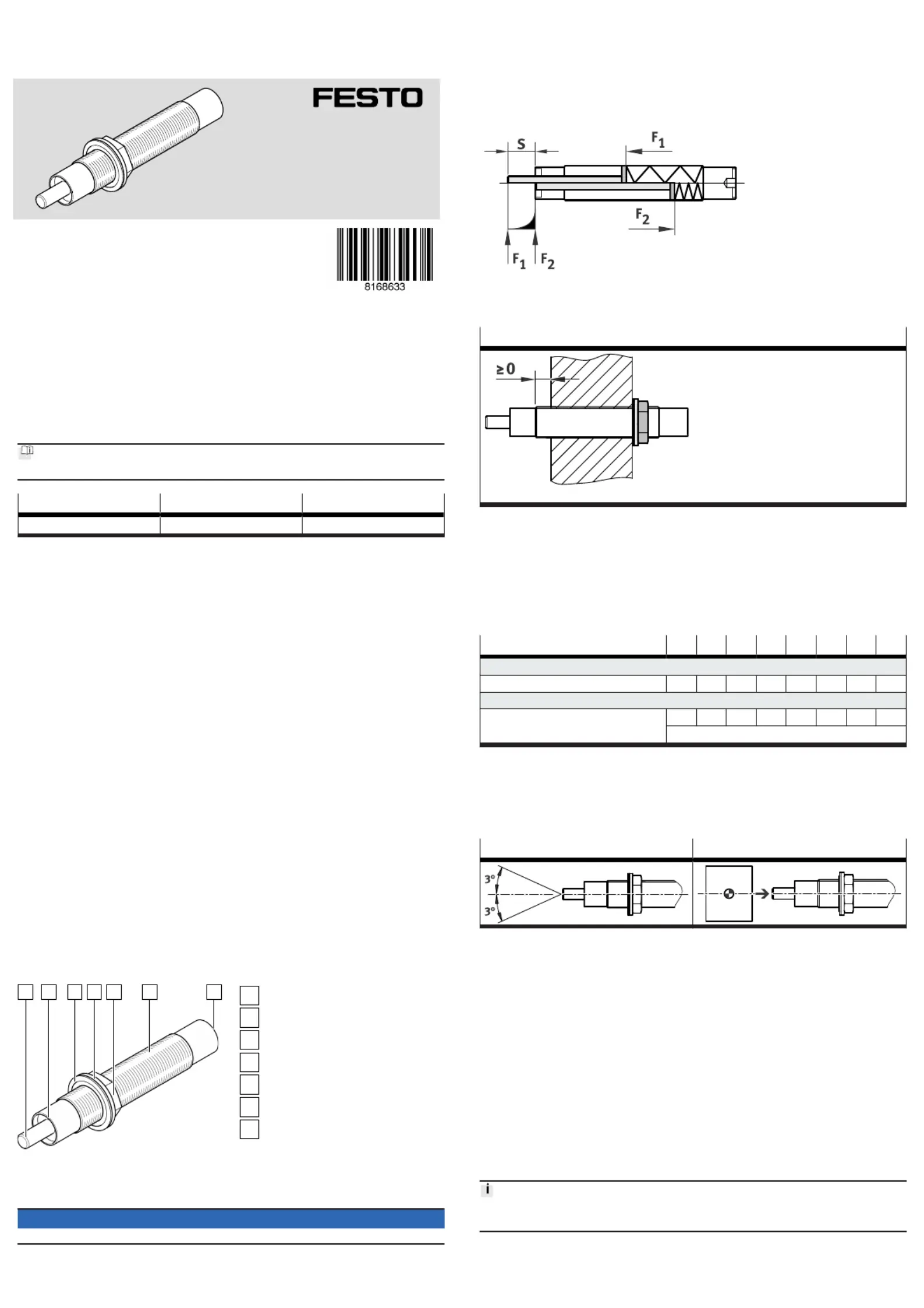
4.2 Function
Insertion force F2 acting on the buffer moves the piston rod of the hydraulic shock
absorber through the cushioning length s to the fixed stop to the end position.
When the piston rod is retracted, the hydraulic fluid in the shock absorber flows
through a path-dependent flow control valve and cushions the motion.
If the insertion force is less than the reset force F1 of the internal compression
spring, the piston rod returns to the initial position.
F1 Reset force
F2 Insertion force
s Stroke/cushioning distance
Tab. 2: Function
5
Mounting product
Lock nut mounting on one side
The mounting surface must not protrude beyond the thread area.
Tab. 3: Mounting in thread
1.
Screw in the product up to the intended stop position.
The order of installation of the washer and sealing washer must be followed
to guarantee a tight seal to the pressure chamber (lock nut, washer, sealing
washer).
Do not exceed the maximum torque when screwing or holding the internal
hexagon socket/slot.
2.
Tighten the lock nut to the tightening torque.
DYSD-... -5 -7 -8 -12 -16 -20 -25 -32
Internal hexagon/slot
Max. torque [Nm] 0.5 1.5 3 6 12 20 25 50
Lock nut
Tightening torque [Nm] 2 3 5 20 35 60 80 100
Tolerance ± 20%
Tab. 4:
Torques
5.1 Aligning product
–Observe the axial direction of force of the moving mass to the axis of the shock
absorber.
–The mass must contact the piston rod and the fixed stop over a wide area.
Force direction, max. deviation Alignment of the mass
Tab. 5:
Permissible axial force direction and alignment of the moving mass
6 Commissioning
6.1 Executing test run
1. Start the test run at the drive at reduced velocity.
2.
If necessary, readjust the position of the shock absorber.
3. Gradually increase the velocity of the drive to the operating value in steps.
Ä
If set correctly, the end position is reached without a hard stop.
With hard stop:
–
Reduce the impact velocity if necessary.
–Check function and design of the shock absorber.
6.2 Notes on operation
Energy absorption
• Only use the shock absorber within the permissible range of 25 % … 100 % of
the maximum energy absorption
è
10 Technical data.
Recommendation: use the shock absorber within the optimum range from
50 % … 80 % of the maximum energy absorption.
Problemløsning Festo DYSD-Q11-32-25-Y1F-L-Y10
Hvis du har læst manualen omhyggeligt, men ikke fundet en løsning på dit problem, bed andre brugere om hjælp
Specifikationer
| Mærke: | Festo |
| Kategori: | Ikke kategoriseret |
| Model: | DYSD-Q11-32-25-Y1F-L-Y10 |